
Chapter 1 Introduction
1.1 Feature Highlights
F108 is a racing drone which can fly at high speed even in PosHold Mode. It is suitable for beginners to professional FPV racing. It uses unique inertial guidance algorithm to solve the problem of losing control when optical flow information is unavailable during high-speed flight or being unable to fix the point when the joystick is released during flight. The updated Kalman fusion algorithm addresses the issue of open-source flight control being limited to altitude determination based solely on terrain in optical flow PosHold mode, so it can schieve precise flying. It supports 5 flight modes, including PosHold mode, Alt-Hold mode, Stabilize mode, Manual mode, and Turtle mode. Even newcomers can achieve stable flight for the first time.
1.2 Overview of F108
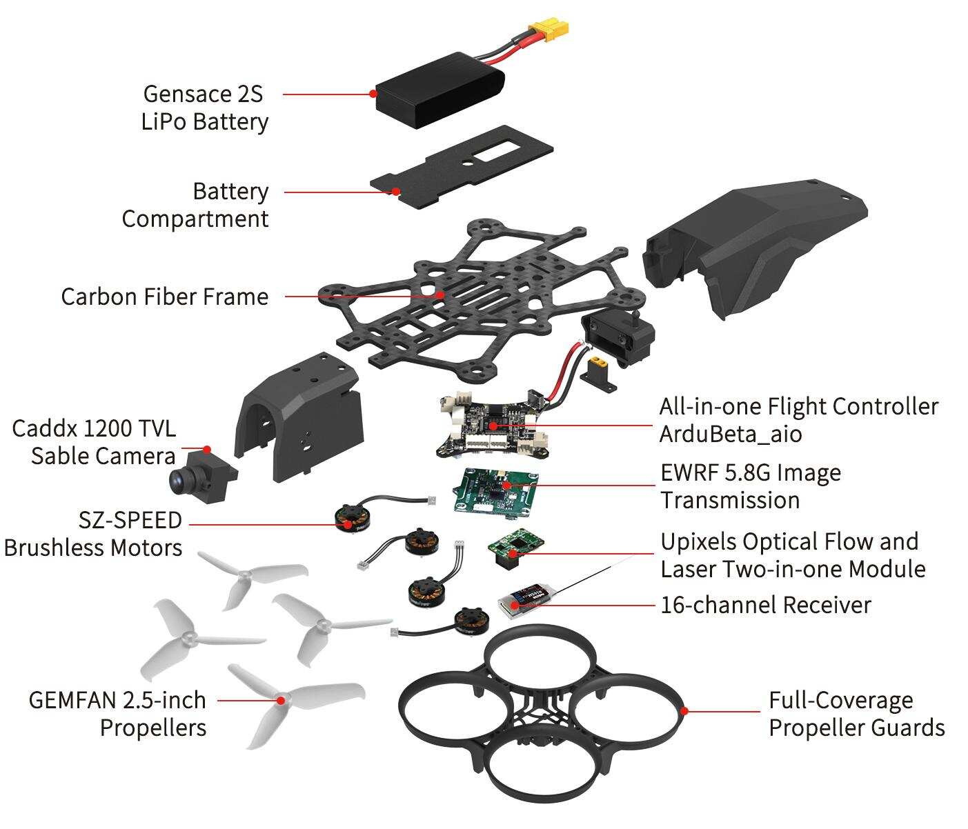 Parts Introduction
1.3 Package List
Name | Details | PNP Version | RTF Version | (Analog Video Transmission) | (Analog Video Transmission with Monitor) | (Analog Video Transmission with Goggles) |
F108 Frame | F108 Frame | 1 | 1 | 1 | 1 | 1 |
Transmitter | RadioLink T8S | 1 | 1 | 1 | ||
Receiver | RadioLink R16SM | 1 | 1 | 1 | ||
FC/ESC | RadioLink All-In-One Flight Controller ArduBeta_aio | 1 | 1 | 1 | 1 | 1 |
Optical Flow | Optical Flow and Laser Two-in-one Module | 1 | 1 | 1 | 1 | 1 |
Motor | SZ-SPEED Motor | 4 | 4 | 4 | 4 | 4 |
Propeller | Gemfan Propeller | 4 | 4 | 4 | 4 | 4 |
Battery | Gensace 2S XT30 Battery | 1 | 1 | 1 | 1 | 1 |
Charger | RadioLink CM210 | 1 | 1 | 1 | 1 | 1 |
Analog Video Transmission | Video Transmission | 1 | 1 | 1 | ||
Camera | sable Camera | 1 | 1 | 1 | ||
Goggles | ZENGHANSI 3 inch FPV Goggles | 1 | ||||
Monitor | Hawk eye All-in-one 4.3 inch FPV Monitor | 1 | ||||
Camera Mounting | DJI O4 Camera Mounting | 1 | 1 | 1 | 1 | 1 |
Hex Wrench | 1.5mm Hex Wrench | 1 | 1 | 1 | 1 | 1 |
Screwdriver | 2.0mm Screwdriver | 1 | 1 | 1 | 1 | 1 |
Package | Portable Bag/Package Box | 1 | 1 | 1 | 1 | 1 |
Note:
T8S is used as an example in the manual of F108. Users can choose other RadioLink transmitters to control F108 such as T16D/T12D/T8FB.
Please refer to the sales interface for the actual packing list.
Please tear off the sticker of the optical flow lens, otherwise the positioning accuracy will be affected.
For F108 with analog video transmission system, please remove the camera lens protective cover, otherwise the image is not available. In addition, the camera angle is adjustable.
Chapter 2 Before Flight
2.1 Transmitter
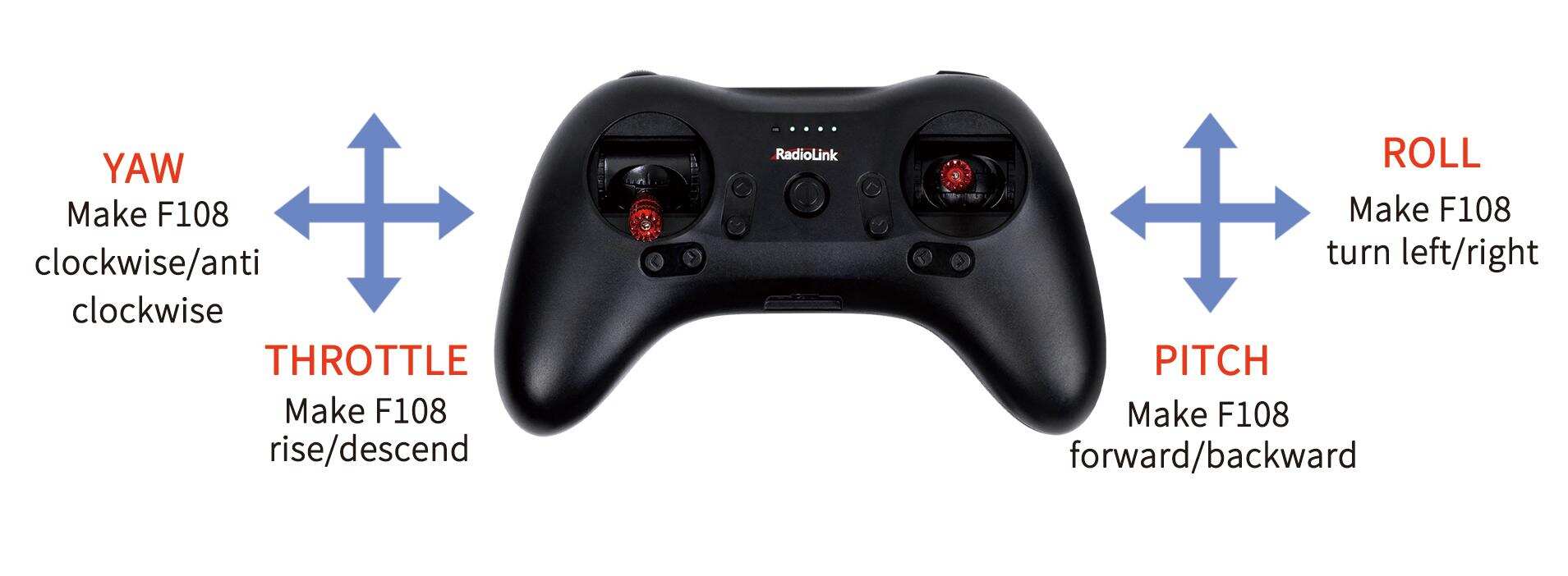
The two joysticks of T8S correspond to the four basic channels respectively.
Note: All of the following are based on RadioLink T8S Mode 2 (Throttle on the left stick).
Left joystick
Make the F108 rise or descend by toggling the left stick (THROTTLE) vertically upward or downward and turn clockwise or anticlockwise by toggling the left stick (YAW) to the left or right.
Right joystick
Make the F108 fly forward or backward by toggling the right stick (PITCH) vertically upward or downward and to left or right by toggling the right stick (ROLL) to the left or right.
MODE 2
2.2 Joysticks & Flight Movements
A. Throttle: Rise/ Descend/Hover (Note: Take T8S mode 2 as an example)
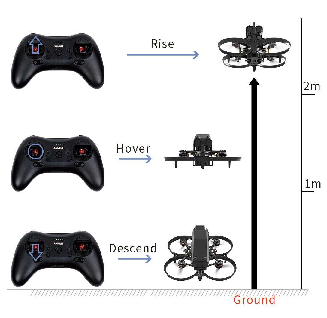
Toggle the throttle stick (on the left) vertically upward and F108 will rise and toggle the throttle vertically downward, then F108 descends.
B. Yaw: Clockwise/Anticlockwise
Toggle the yaw stick (on the left) to the left and F108 will turn anticlockwise and toggle the yaw stick to the right, then F108 turns clockwise.
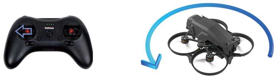
Yaw stick to the left, F108 turns anticlockwise
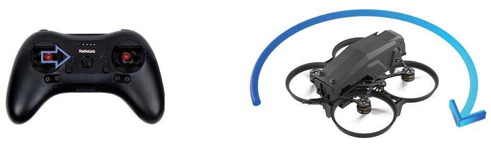
Yaw stick to the right, F108 turns clockwise
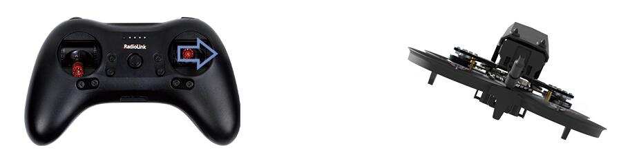
C. Pitch: Forward/Backward
Toggle the pitch stick (on the right) vertically upward and F108 will fly forward and toggle the pitch stick vertically downward, then F108 flies backwards.
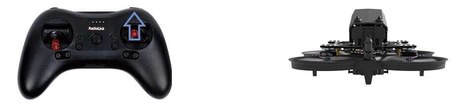
Pitch stick upward, F108 moves forward
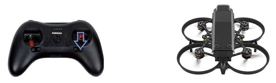
Pitch stick downward, F108 moves backward
D. Roll: Right/Left
Toggle the roll stick (on the right) to the left and F108 will fly to the left side and toggle the roll stick to the right, then F108 will fly to the right side.
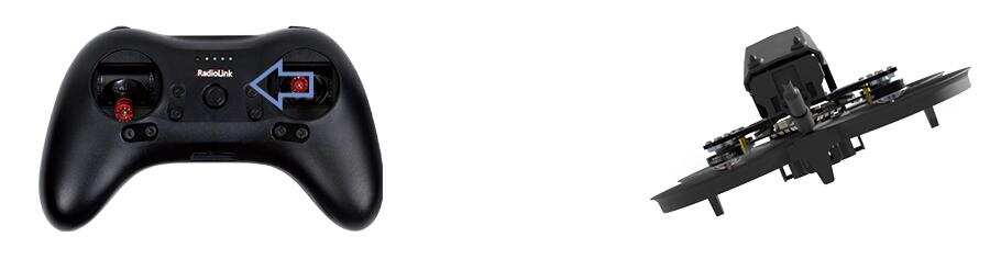
Roll stick to left, F108 fly to the left side
Roll stick to right, F108 fly to the right side
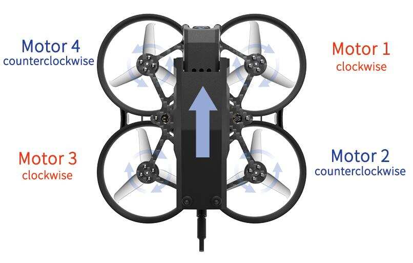
2.3 Motor and Propeller Installation
To make the aircraft fly, motors usually rotate clockwise (CW)/counterclockwise (CCW) with the propellers. It is very important to make sure about the rotation direction as below when installing motors. Otherwise, the drone would fail to take off.
Motor and propeller installation can be skipped as F108 is already assembled by factory default. If any of the motors is worn out and needs to be replaced, it is essential to identify the correct motor/propeller rotation. Please follow the below picture to install the motor and propeller.
2.4 Power Supply
Power for transmitter T8S: Make sure the transmitter T8S is fully charged.
Power for F108: The voltage of 2S LiPo battery packed with F108 by default is not fully charged, so the battery needs to be charged with the charger CM120 before flight. For the instruction manual of CM210, please refer to the Chapter 3.5 Charger.
2.5 Flight Notes
If it is the first time of flying drone for the pilot, Altitude Mode is strongly advised to set. At the Altitude Mode, when toggle the throttle upward till the drone reaches a certain height and release, F108 will remain at this height. It is simpler because pilots only need to toggle the other joystick to make the F108 move forward/backward or turn left/right. If it is the Stabilize Mode especially Manual Mode chosen, try to toggle the joysticks slightly to correct the flight and avoid the drone having sudden moves.
If F108 drops by hitting something, toggle the throttle joystick to the bottom position immediately to stop motor rotation.
2.6 Flight Controller Channel Introduction
Mode | CH5 | CH7 | CH8 | CH10 |
Arm | (servo output +100% or 100%) | |||
Stabilize mode | (servo output -100% or 0%) | |||
Alt-Hold mode | (servo output 0% or 50%) | |||
PosHold mode | (servo output +100% or 100%) | |||
Turtle mode | (servo output +100% or 100%) | |||
Manual mode | (servo output +100 or 100%) |
2.7 Setup Transmitters
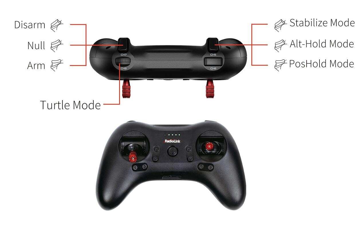
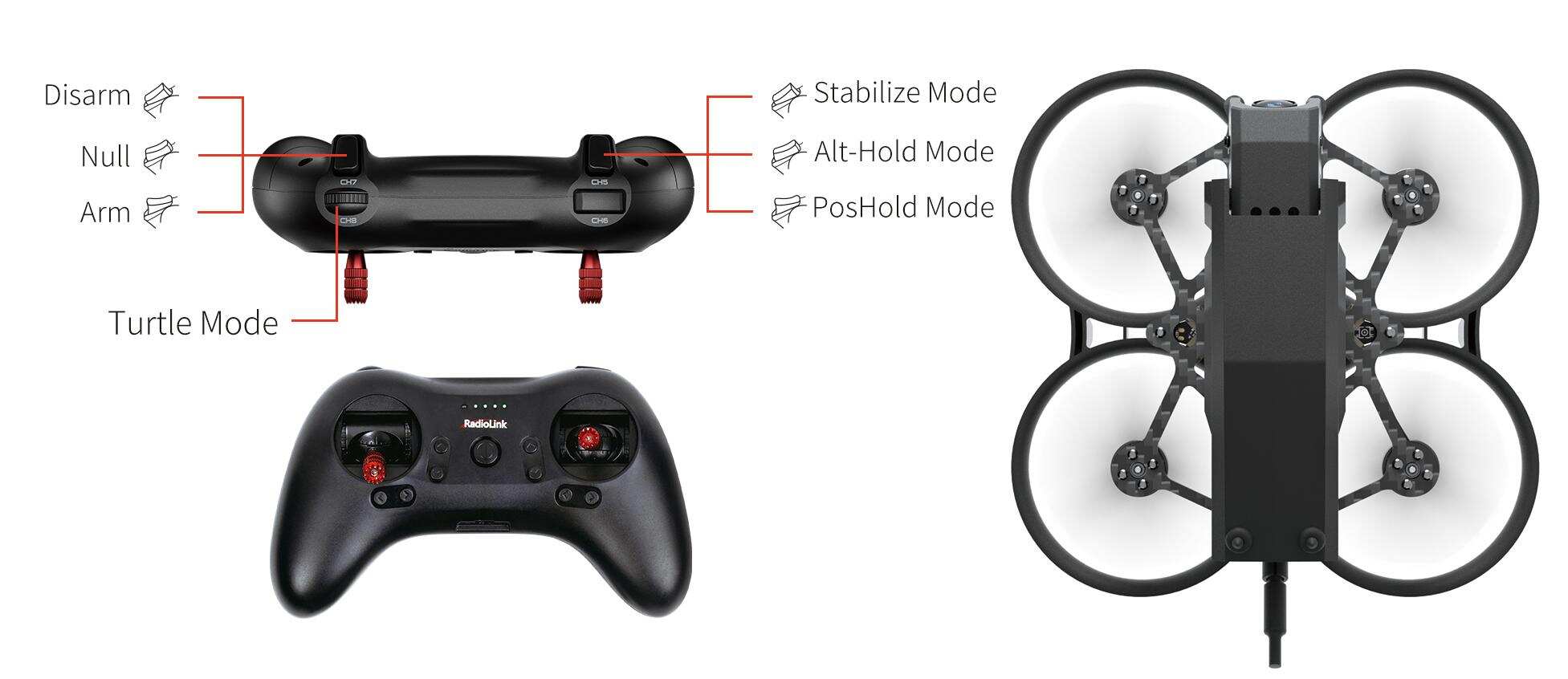
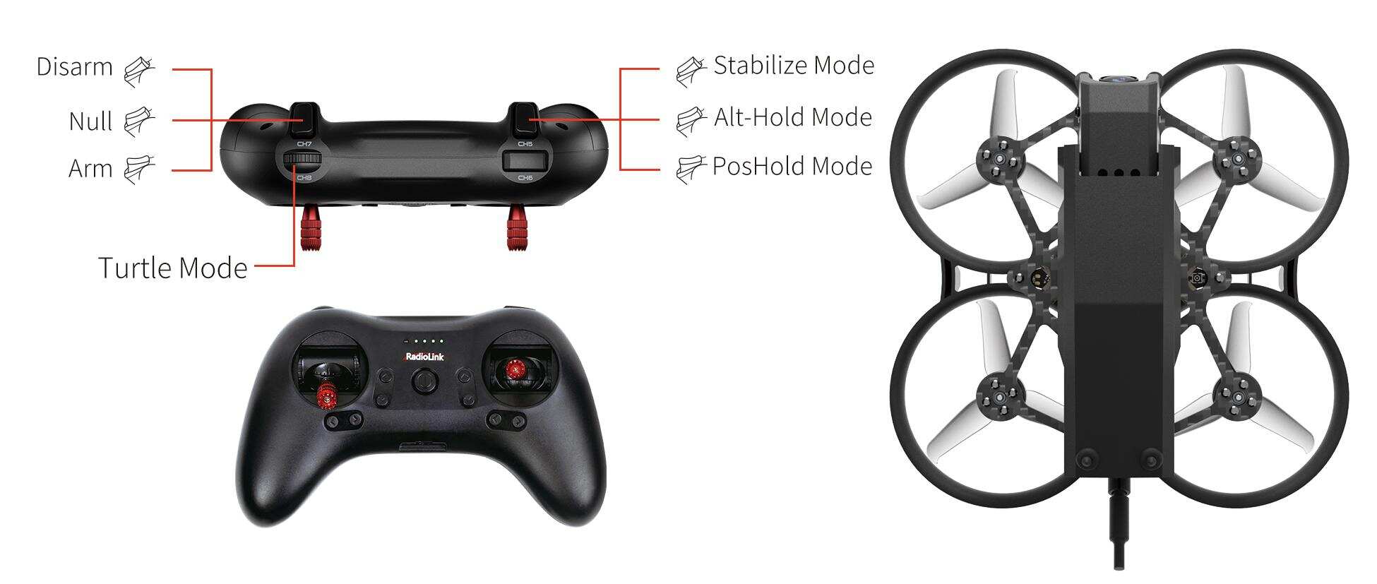
T8S Transmitter
When T8S is used to control F108, PosHold mode, Alt-Hold mode and Stabilize mode are controlled by CH5 of T8S. CH7 of T8S is used to arm/disarm the aircraft. CH8 of T8S (Roll to the far right to turn it on; roll to the far left to turn it off) is used to switch the turtle mode, as shown below:
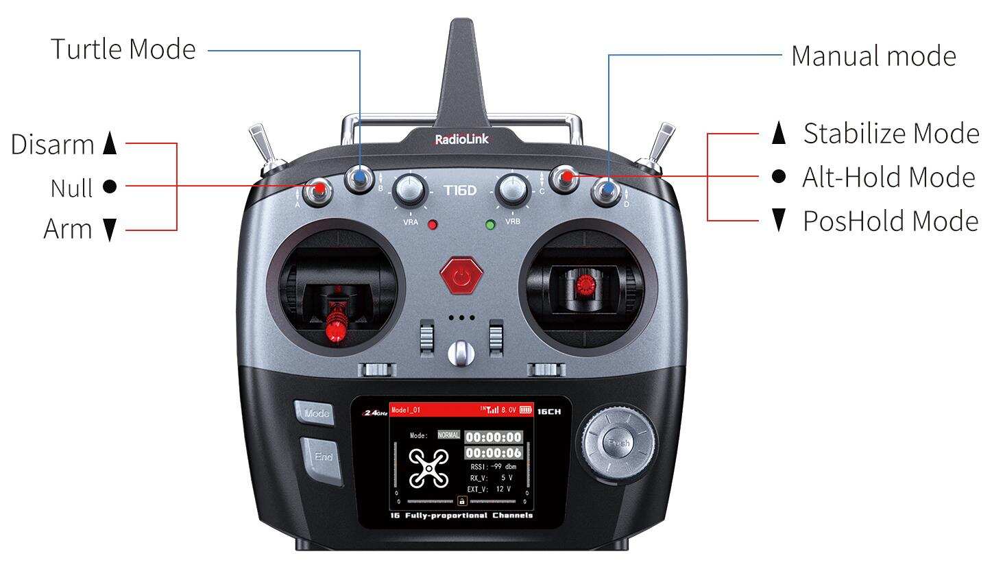
T16D/T12D Transmitter
When T6D/T12D is used to control F108, SWC for CH5 is used to select PosHold mode, Alt-Hold mode and Stabilize mode; SWA for CH7 to arm/disarm F108, SWB for CH8 to turn on/off the turtle mode (Push SWB up to turn it off. Push SWB down to turn it on). CH10 control manual mode by default (Push SWD up to turn it off. Push SWD down to turn it on), as shown below:
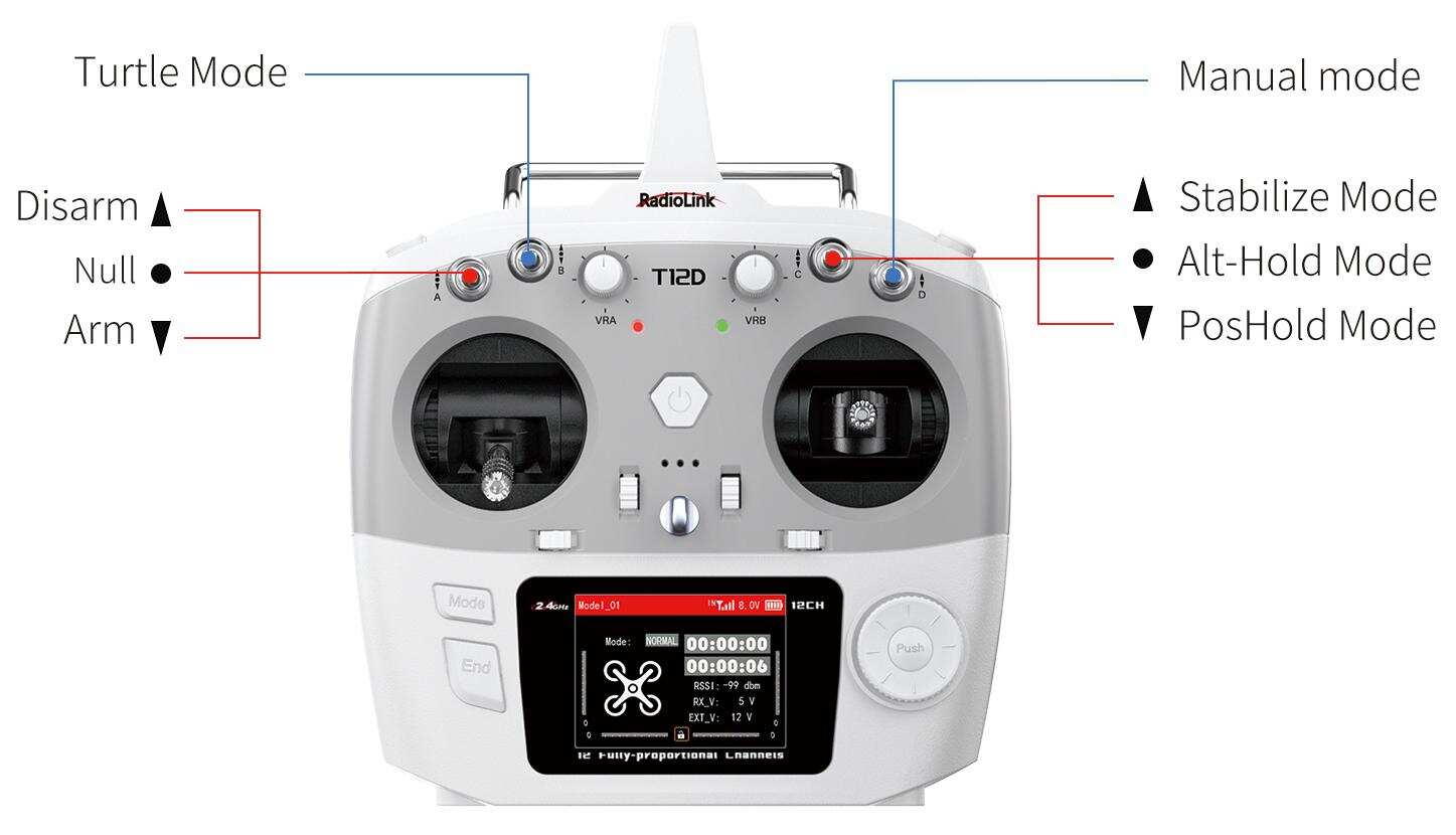
* For more setting instructions of different RadioLink transmitters, please visit www.radiolink.com to download the corresponding detailed manual.
2.8 Binding
F108 RTF version comes with R16SM receiver (As shown below).
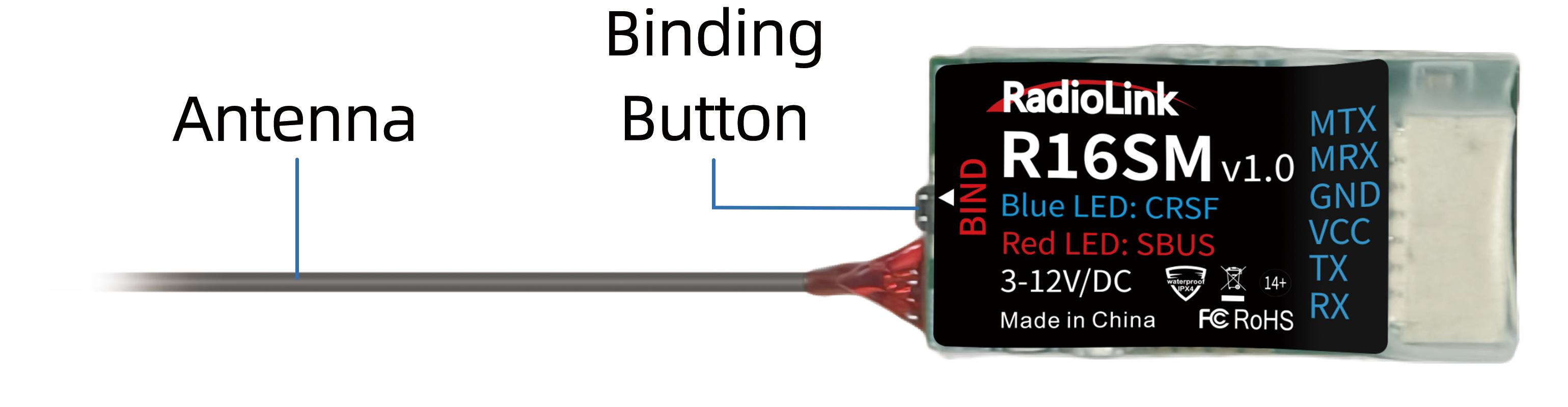
If it is the RTF version purchased, there is no need to bind because the binding between the transmitter and R16SM receiver is complete by factory default. However, if you want to change the transmitter or receiver, binding between the transmitter and receiver needs to done first.
Here are the binding steps for RadioLink transmitter and receiver:
① Place the transmitter and receiver close to each other within 50 centimeters.
② Power on the transmitter and the receiver.
③ There is a black binding button on the side of the receiver. Press it for more than 1 second. When the LED starts flashing, meaning binding process has started.
④ The binding is complete when the LED is always on.
For transmitter and receiver from other brands, please refer to its detailed manual for binding steps.
Note: Please always make sure the LED of R16SM is blue, meaning CRSF protocol. If the LED is red (SBUS working mode), please press the binding button once to change it to blue.
Chapter 3 Flight at Different Flight Modes
3.1 Power on F108
After T8S and the battery are fully charged, put the throttle stick of T8S at the lowest position and long press power key to power on T8S. Then plug the XT30 end of the battery into the F108, then fix the battery with the strap.
Notes when powering on F108:
Make sure the head points to the same direction as the pilot when powering on and be ready to fly to ensure safety.
When powering up the F108, the red wire of the battery corresponds to the silkscreen +, and the black wire corresponds to the silkscreen -. The positive and negative poles of the battery cannot be connected in reverse, otherwise the aircraft will be damaged.
After powering on, the red status indicator of F108 will start flashing. Wait until the red status indicator is solid, which means the self-test is complete F108 is ready to arm and take off. If the red status indicator keeps flashing, F108 cannot be armed. Please troubleshoot it by checking the connection, receiver binding and the battery voltage.
3.2 Arm and Disarm F108 (Take T8S as an example)
Arm F108
Please arm F108 before the flight. Otherwise the aircraft will not take off even if the throttle is pushed to the highest position.
Put the throttle stick at the lowest position. Push CH5 to select a flight mode. Push up the CH7 switch to arm F108. F108 propellers start to rotate at idle speed indicates arm successful. For security reasons, F108 will be disarmed automatically if there is not any operation of the throttle for 5 seconds. Please arm F108 again when the flight is ready.
F108 propellers start to rotate at idle speed indicates arm successful
Disarm F108
When the flight is finished, push down the CH7 switch of T8S to disarm F108. F108 propellers stop rotating indicates disarm successful.
Note: When the flight is finished, always make sure F108 is disarmed when get close and try touching it to avoid unexpected harm. Please turn off F108 before T8S.
F108 propellers stop rotating indicates disarm successful
3.3 Five Flight Modes
3.3.1 PosHold Mode
Rise/Descend
Press up the CH5 switch of T8S, which makes F108 fly at Altitude Hold Mode. Make sure the head points to the same direction as the pilot when powering on. Then arm F108 and push the throttle joystick vertically upward higher than center position, then the F108 will rise while if push it vertically downward, then the F108 will descend.
Hover
Push the throttle joystick vertically upward till the F108 rises to a height as wish, then toggle it back to center position and release, the F108 will hover at this height.
Forward/Backward/Right/Left
In PosHold mode, F108 can fly forward/backwards or towards to right/left by toggling the right stick at the certain height. F108 is a racing drone, so the reaction speed is very fast. It is advised to release the stick as soon as toggle to one direction so that F108 will back to level automatically. Otherwise, F108 will keep flying to the toggled direction with accelerated speed. Please note that the nose of the aircraft is facing the front of the person, in the same direction as the person. Once the direction of the aircraft changes due to the wrong movement of the direction stick, pull down the throttle stick to land the aircraft.
Clockwise/Anticlockwise Rotation
When get familiar with the above flights, try flight clockwise/anticlockwise because the yaw practice is more difficult to judge the flight direction. Clearly knowing the direction will quickly help master drone flight. Try imagine sitting on the drone could be a better way to practice.
3.3.2 Alt-Hold mode
F108 has altitude-hold (Alt-Hold) mode. The operation method is basically the same as PosHold mode. However, when the throttle is stabilized to control the altitude, the aircraft cannot maintain the current position. Without the joystick control, it will drift in any direction of the plane. In addition, it does not have a brake function when the joystick is released. The aircraft needs to be controlled by the pitch and roll joysticks to move forward/backward and left/right.
3.3.3 Stabilize Mode
The basic operation such as Rise/Descend/Forward/Backward/left/right of Stabilize mode is the same as Alt-Hold mode. In Stabilize mode, the throttle corresponds to the aircraft power. The more the throttle stick is pushed up, the greater the climbing power. The flight control no longer assists in altitude setting. If you want the aircraft to maintain the same altitude, the pilot needs to practice for a period of time to achieve it through flight operations.
However, in Stabilize mode, the flight controller has a limit on the maximum flight angle of the aircraft. Manual rolls cannot be performed in in Stabilize mode. If you want to achieve continuous rolls, please switch to manual mode.
3.3.4 Manual Mode
The basic operation such as Rise/Descend/Forward/Backward/left/right of Manual mode is also the same as Alt-Hold mode. Manual mode is a classic FPV flight control mode. In this mode, all flight assistance functions such as automatic stabilization will be turned off. The remote control sticks directly control the throttle and attitude of the aircraft. Please switch to this mode on the premise of mastering flight control skills.
In manual mode, the aircraft attitude control sensitivity will be greatly improved compared with Alt-Hold mode and Stabilize mode. The attitude is not restricted and can reach any attitude. Users can achieve racing and fancy flying.
After you are familiar with basic operation such as Rise/Descend/Forward/Backward/left/right in Alt-Hold mode and Stabilize mode, you can assign a switch to the channel 10 (CH10) to switch to manual mode, and practice advanced actions such as continuous rolls, fancy flying, etc.
3.3.5 Turtle Mode
When the aircraft is hit or flips over at any angle due to operation error, you can enable the turtle mode to rotate one side of the motor to flip the fuselage back to the upright position. Channel 8 (CH8) is used to enable the turtle mode. (When turning on/off the turtle mode, the throttle stick must be at the lowest point. Otherwise you cannot turn on/off the turtle mode). After turtle mode is turned on, push up the throttle stick a little bit. Move the corresponding roll or pitch stick in the direction you want to flip (For example, if you want to flip to the right, move the roll stick to the right). After the fuselage flips back to the level, put down the throttle stick to the lowest position. Turn off the turtle mode. Then arm F108 and take off.
3.4 Low Battery Alarm
When the battery voltage is lower than 6.8V, the red indicator light on the flight controller of F108 starts to flash slowly (If a 3S lipo battery is used, the red indicator will flash when the battery voltage is lower than 10.5V). Please return home immediately and replace the battery to avoid over-discharge. F108 video transmission version comes with a camera which has OSD function. The pilot can check the current voltage of the aircraft battery on the FPV screen or goggles.
After the red indicator light has started to flash because of the low voltage for 3 seconds, the aircraft will automatically land slowly. The roll and pitch stick can be used to adjust the landing position. F108 won’t respond to the throttle stick at this time.
Note: F108 comes with a 2S battery. If you want to use a 3S battery, you need to flash the parameters which are compatible with 3S battery. For more details, please refer to Radiolink official website www.radiolink.com/f108_firmware
3.5 Level Calibration
Level calibration has been done bu factory default. You can fly it directly without calibration. If the aircraft becomes unstable after a collision or if you replace the motor or propeller, please re-calibrate the aircraft. F108 is in disarmed state when calibration. Here are the steps of level calibration:
The flight controller ardubeta_aio successfully connects to Mission Planner via the TYPE_C data cable (It can also be connected via digital transmission. Please note that when connecting via digital transmission, the baud rate should be 57600, while when connecting via TYPE_C cable, the baud rate should be 115200). Ensure that the receiver is bound to the transmitter successfully, and then power on both F108 and transmitter.
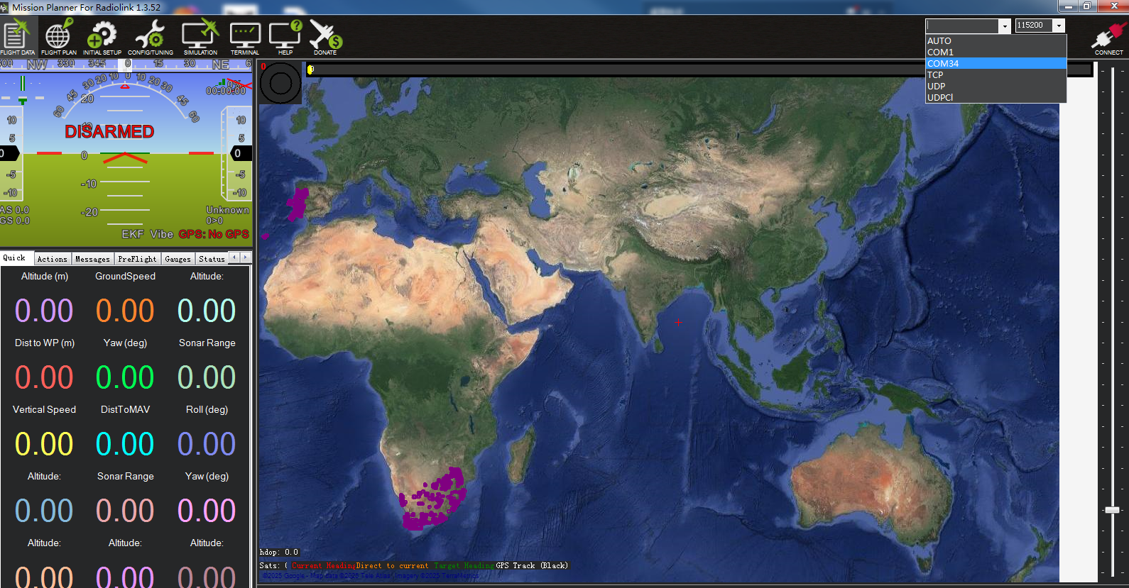
Open Mission Planner (F108 supports RadioLink Mission Planner, ArduPilot Mission Planner and QGC Mission Planner. The download link of the Mission Planner: https://www.radiolink.com/f108_firmware). Select the baud rate and port, and click "Connect" to connect to the flight controller.
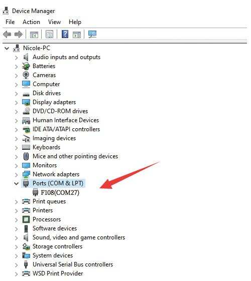
Note: Ports varies from different computers. Please select the correct port to connect. Connection may fail with several ports in use. Please remove the other connections, or enter Device Manager to view the port of the flight controller of F108, just as below. (F108 is not recognized by the computer by default unless you have installed the driver. Please refer to RadioLink official website for the guide on how to install the driver on the computer.)
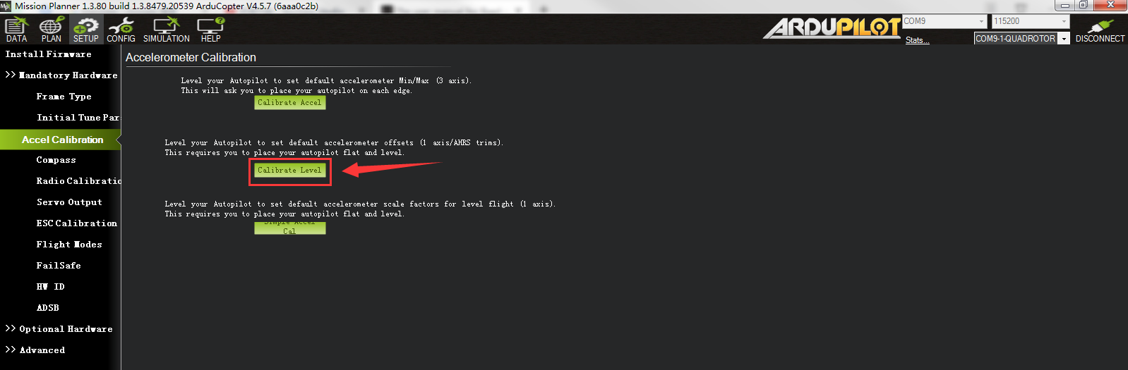
Click Setup-- Mandatory Hardware-- Accel Calibration. Put F108 on a level surface. Then click Calibrate Level to start the calibration, and wait for about two seconds until the word "Complete" appears, indicating that the level calibration is complete. Please re-power F108 after the level calibration is done.
3.6 The Receiver Connection for F108 PNP
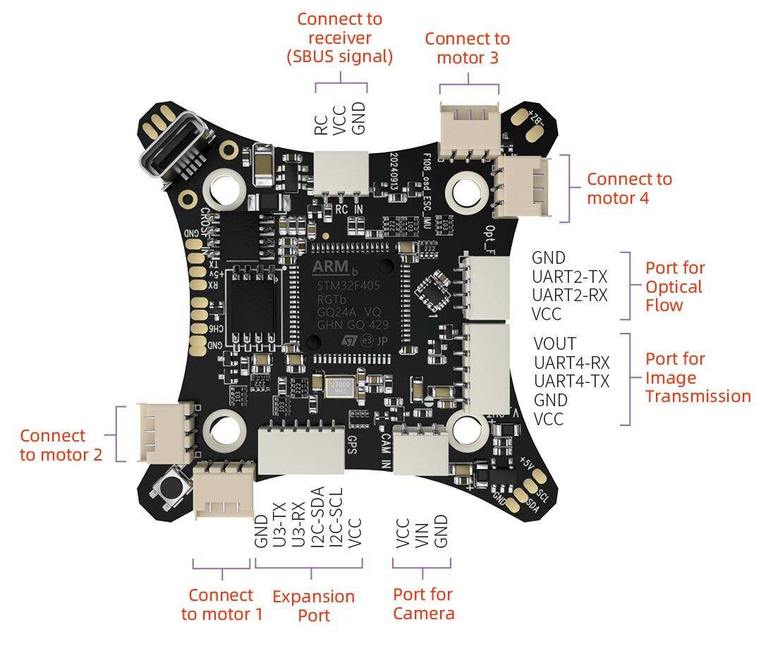
F108 PNP version does not come with transmitter or receiver, so the pilot needs to prepare the receiver that supports SBUS or ELRS protocol. The receiver needs to connect to the flight controller. Here is the socket introduction of the flight controller of F108:
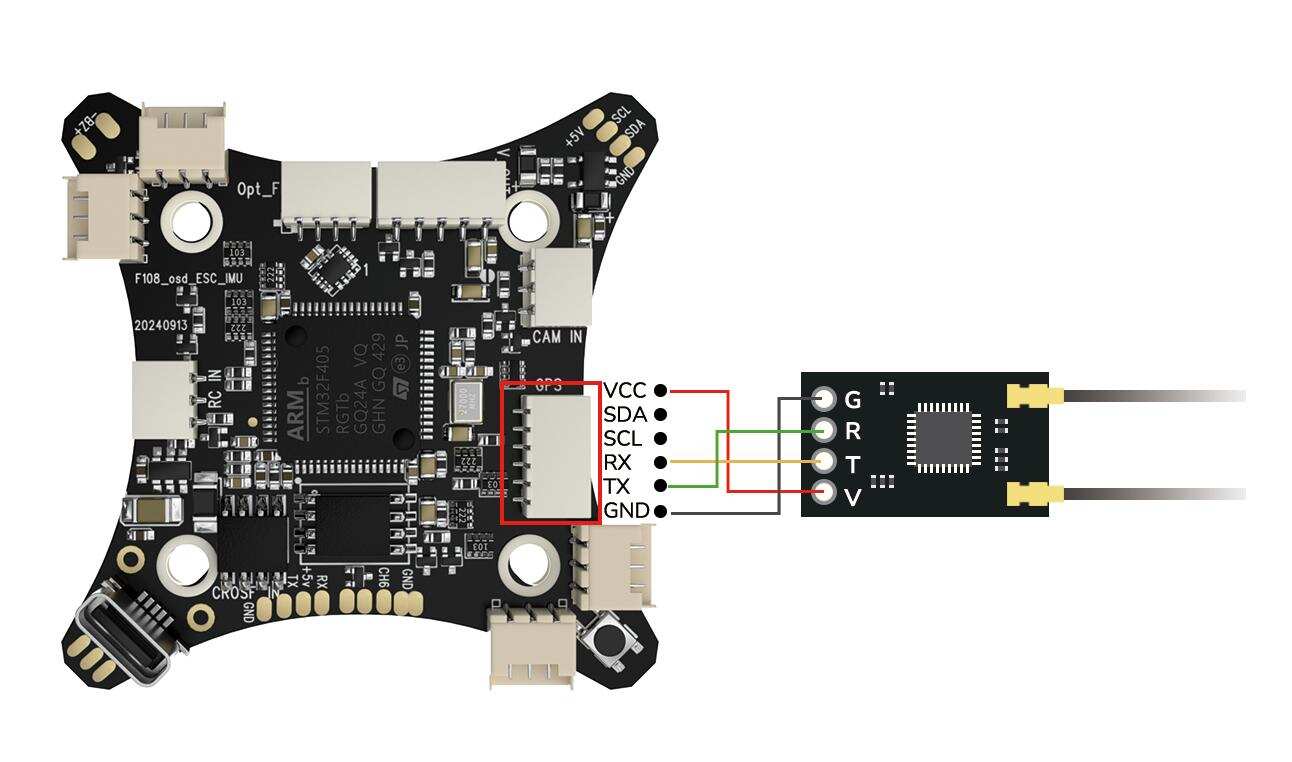
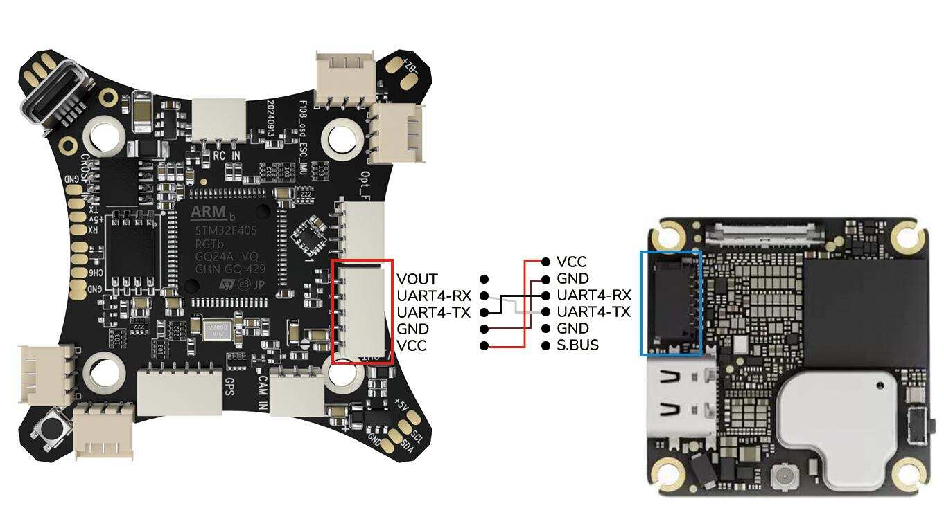
If the ELRS receiver is used with F108, please connect the ELRS receiver to the expansion port of the flight controller, as shown below:
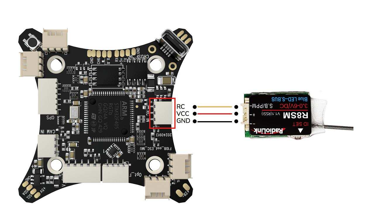
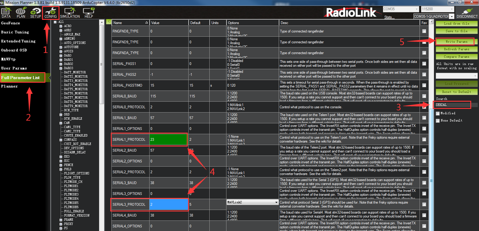
If SBUS receiver is used with F108, please connect SBUS receiver to the SBUS signal port of the flight controller (As shown below. Take R8SM as an example). Since the factory configured receiver serial port is serial port 3 (The 6 pin expansion port for ELRS receiver), you need to modify the settings when using the SBUS receiver, otherwise there will be conflict between the SBUS serial port and the expansion serial port, resulting in the failure of the communication between the transmitter and receiver. Please connect the flight controller to Mission Planner. Click CONFIG--Full Parameter List. Search for SERIAL. Change the value of SERIAL3_PROTOCOL from 23 to 2. Change the value of SERIAL1_PROTOCOL from 2 to 23. And then click Write Params. The steps are shown below:
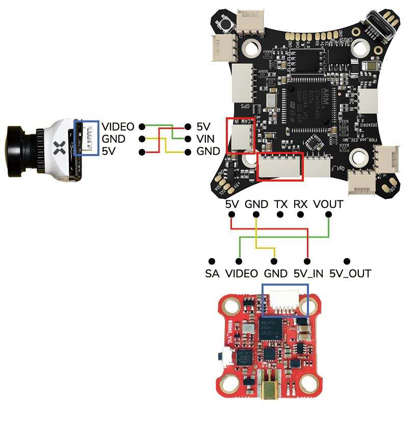
Here is the connection diagram of the analog video transmission and the camera to F108:
Here is the connection diagram of the digital image transmission to F108:
Note: If you want to output RSSI value from receiver to FPV, please refer to the link below to set parameters:
https://www.radiolink.com/newsinfo/504912.html
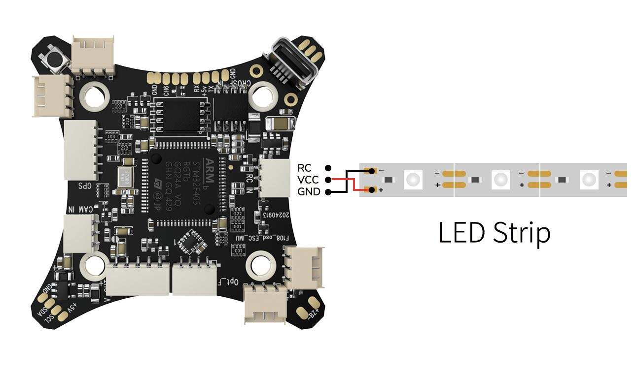
Users can mount LED strip on F108. Here is the connection diagram of the LED strip to F108:
Note: LED strip does not come with F108. Users need to buy it separately.
3.7 Charger
F108 is packed with RadioLink CM210 balance charger (Only for 2S lipo battery) to charge the battery.
CM210 Specifications:
Size: 40.5*21*15 mmWeight: 9g
Input Voltage: 5VSupporting Battery: 2S LiPo battery
Charging Precision: 0.02VCharging Voltage: Max. 4.2V for each battery cell
Charging Current: 1.5ABalance Current: 0.8A
Max. Output Power: 20WPower Supply Input Port: USB Type-C Input
Charging Port Interface: 3P XH2.54 port
Working Modes: Charging Mode, Balance Mode, Repair Mode (Self-adaptive, with no need to set it)
The connection of CM210, battery, cable is as shown below:

Instructions for using CM210 charger:
Insert one end of the standard USB cable into the Type-C input port of the CM210 charger (as shown in the picture above), and then connect the other end of the USB cable to power supply equipment such as power bank, computer, mobile phone adapter, etc.. After the right connection, the red LED indicator will be always on.
Insert the balance port of the standard 2S lithium battery of D460 into the charging port of CM210 (as shown in the picture above). Then the green LED indicator starts flashing, which means it starts to charge the battery. (Note: The green LED indicator flashes during the charging to indicate normal charging; If the red LED indicator flashes during the charging to indicate abnormal charging. Please reconnect battery and cable to troubleshoot the abnormality.)
When all four LED indicators turn solid green, the battery is fully charged, and the charger will automatically stop charging.
Remove the battery and then disconnect the power supply.
CM210 LED indicator status:
LED color | Status | Meaning |
Red | Flash | The charger detects abnormality. |
Always on | No battery is connected. | |
Green | All four green LEDs flash once. | The charger is powered on. |
The first green LED flashes, and the other LEDs are off. | The battery voltage is lower than 7.4V. | |
The first gre | The battery voltage is lower than 7.8V. | |
The front two green LEDs are always on, and the third green LED is flashing. The other LEDs are off. | The battery voltage is lower than 8.2V. | |
The front three green LEDs are always on, and the fourth green LED is flashing. The other LED is off. | The battery voltage is lower than 8.4V. | |
All four green LEDs are always on. | The battery is fully charged. |
Troubleshooting for CM210 charger:
1. After the charger is powered on, the red light flashes just after inserting the battery or within one minute.
The current detection resistor is burned out, and the MCU detects that the current is too large.
The switch tube is damaged, so it is unable to switch normally. There is no current output or the output current of the power supply is too small.
2. After the charger is powered on, insert the battery and charging works normally for a period of time, and then the red light flashes.
The output current of the power supply is too small, or the battery is damaged.
Solution: Replace the power supply or battery to charge it again, if the abnormal phenomenon still occurs, the charger is damaged.
Chapter 4 Instruction Manual of Other Devices
F108 Analog Video Transmission version comes with ZENCHANSI 600mW analog video transmission and CADDX stable camera. If it is the image transmission version purchased, the binding between F108 and the FPV screen/monitor has been done by factory default. Pilots only need to power both on before flight.
4.1 ZENCHANSI 600mW Analog Video Transmission
Overview

LED indicator
The red LED indicates the state of working mode or the item when setting the VTX (flashing 1 time means selecting the channels, flashing 2 times means selecting the bands, flashing 3 times means selecting the power levels).
The blue LED indicates the state of Pitmode or the value of item when setting the VTX (e.g. when selecting the channels, 3 times of flashing means channel 3. When selecting the bands, 3 times of flashing means band C.As for the item of power levels,3 times of flashing means at the power level of 600mW).
Working mode indication
After powering up, the red & blue LEDs will signal the following three items of VTX in turn: channel, band and power level(the flashing times of the red and blue LEDs indicate the item and the value respectively).
After that, the LEDs indicate the working modes.
Normal: The red & blue LED are on.
Pitmode: the Red and Blue LEDs will be twinkles .
Setting
Setting of channel, band and power
After powering up, the flashing times of the red and blue LEDs indicate the item and the value respectively.
Press and hold the function button until the red LED flash 1 time which means the item of channel selecting, then press the button can select the channels (blue LED flashing times corresponds to the channel 1-8).
Press and hold the function button again, the red LED will flash 2 times which means the item of band selecting, then press the button can select the band (blue LED flashing times corresponds to the band A-R).
Press and hold the function button again, the red LED will flash 3 times which means the item of power level selecting, then press the button can select the power (blue LED flashing times corresponds to the power level).
Finally, press and hold the function button, save and exit the setting of VTX (This step is essential for setting).
Pitmode setting
Press the function button twice will toggle the ON/OFF of Pitmode.
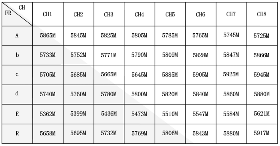
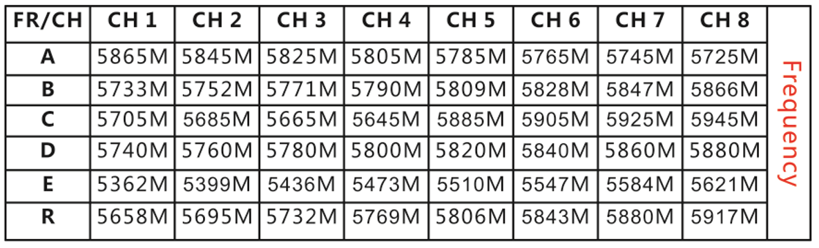
ZENCHANSI 600mW analog video transmission Frequency
Note
Make sure that there is enough space for airflow when installing the module on the drone in case the overheating protection starts to reduce the power even to shut down at the worst.
Please install the antenna before powering up for a longer use life.
4.2 ZENCHANSI FPV Goggles
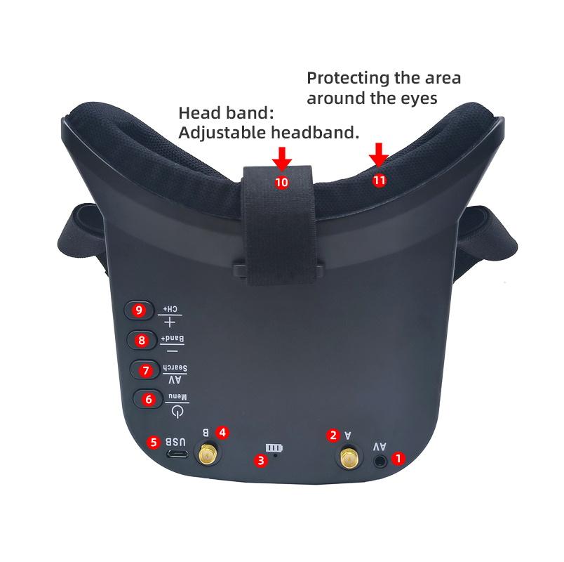
Buttons and Connectors
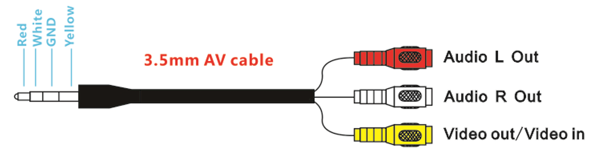
① AV Jack: Output Audio signal in RF receiving mode; Enter the video signal in RF receiving mode.
② A: Antenna port A (RP-SMA Male)
③ EB: Antenna port B (RP-SMA Male)
④ Charging indicator: When it is charging, the red light is on; When it is full, the light is off.
⑤ Micro-USB charging port: Supports 5V/1.5A.
⑥ Power/Menu
Power: Short press into Power ON. Then short press into Menu. Long press for Power OFF.
Menu: Can be adjusted the display parameters.
⑦ AV/Search:
AV: Long press into AV mode. External video signal input should be CVBS, NTSC or PAL.
Search: Short press for Auto-Searching.
⑧-/Band+: Short press the "menu" button to enter the screen parameter setting and select the corresponding parameter. Press "-" to reduce the parameter value.
Band+: Short press for Band+ (Change bands A-B-C-D-E-R circularly).
⑨ +/CH+:
+: Short press the "menu" button to enter the screen parameter setting and select the corresponding parameter. Press "+" to increase the parameter value.
CH+: Short press for Channel+ (Change channels 1-2-3-4-5-6-7-8 circularly).
☆ Menu Display: BRIGHTNESS, CONTRAST, SATURATION and RESET.
AV cable introduction
Frequency
Specifications
☆ Screen size: 3.0 Inches
☆ Resolution: 480*272 pixels
☆ Brightness: 230cd/m²with high brightness backlight LED
☆ Video formats: NTSC/PAL
☆ AV Jack: External video signals input or internals AV signal output
☆ Power Supply Power adapter: DC 5V/1.5A (USB interface)
☆ OSD display: Signal strength; Battery indicator; Channel indication
☆ Battery: 3.7V/1800mAh. Each full charge revive around 3.5 hours working time
☆ Working time: 3.5 hours
☆ Charging time: 3 hours
☆ Antenna connector: RP-SMA (inner pin)
☆ Size: 155*135*55mm
☆ Weight:236.4g (with headband and antennas)
☆ Frequency range: 5362MHz-5945MHz
☆ Channel: 48channels
4.3 Hawk eye 4.3 Inch FPV Monitor
F108 can be equipped with Hawk eye 4.3 inch FPV monitor.
Buttons and functions
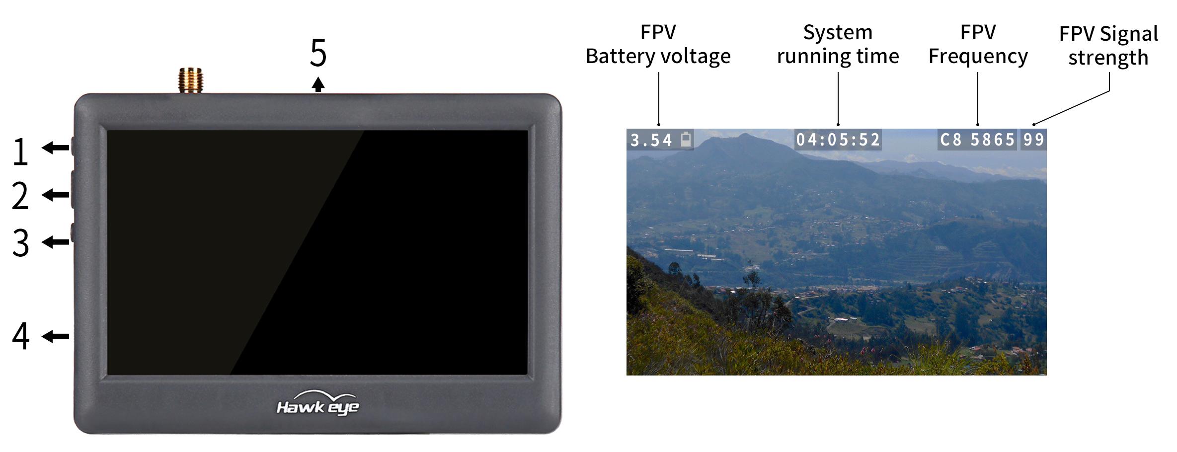
Button Name | Function |
1. Adjustment button(+) | Short press to select desired frequency from 6 groups A-B-C-D-R-F |
2. Power/Menu button | Long press to turn-on/off |
3. Adjustment button(-) | Short press to select desired frequency from groups 1 - 2 - 3 - 4 - 5 - 6 - 7 - 8 |
4. Micro USB Charge port | Charging |
5. Reset | Reset |
Hawk eye FPV monitor frequency group selection

Specifications
LED Screen | Resolution | 480×3(RGB) ×272 |
Backlight | LED | |
Brightness | 250 cd/m2 | |
Aspect ratio | 16:09 | |
Response time | 10ms | |
Color system | PAL/NTSC | |
Battery | Battery life | 1 hour and 40 minutes |
Input | Signal | Video (PAL/NTSC) |
Output | Signal | Video (PAL/NTSC) |
Specification | Monitor size | 113.5mm*79mm*14mm |
Gross weight | 130g | |
5.8G sensitivity | -94 dB |
Chapter 5 Specifications
F108 Aircraft
Weight of Drone (Without Battery): 120g
Takeoff Weight Without Load: 165g
Dimension Frame: 153*153*70mm
Diagonal Length: 110mm
Material Frame: Carbon Fiber
Shell Material: Black TPE fine frosted finish; Camera and Battery Fixing Part: Black ABS and PC fine frosted finishFull-Coverage Propeller Guards: Nylon and Fiber
Flight Time: 7 Minutes
Ascent Speed: 50km/h
Horizontal Speed (at sea level, no wind): 110km/h
Flight Distance: 2000 meters, maximum range is tested in an unobstructed area free of interference
Max Service Ceiling Above Sea Level: Same as the flight distance, the flight distance and height can be set as you need in GeoFence of Mission Planner
Maximum Wind Resistance: Moderate breeze
Flight Modes: It is default with Pos-Hold Mode, Alt-Hold Mode, Stabilize Mode, Manual Mode and Turtle Mode
Positional Accuracy: 20 centimeters
Operating Temperature: -30℃~85℃
Power System
Motor: SZ-SPEED 1303-10000KV Motor
Flight Controller: RadioLink All-In-One Flight Controller ArduBeta_aio with 4-in-i ESC and OSD module integrated
Propeller: Gemfan 2512 Propellers
Battery: Gensace 2S 850mAh 35C XT30 Battery
Remote Control System
Transmitter: RadioLink 8 channels transmitter T8S (T6D/T12D/T8FB is selectable)
Receiver: R16SM
Frequencies Band: 2.4GHz ISM(2400MHz~2483.5MHz)
Transmission Power: <100mW(20dbm)
Control Distance: 3000 meters, maximum range is tested in an unobstructed area free of interference
Optical Flow
Optical Flow: Optical Flow and Laser Two-in-one Module
Operating Voltage: 3.7~5.0V
Operating Current: ≤70mA
Operating Temperature: -20 to 60°C
TOF FOV: HFOV: 20°; VFOV: 17°Measurement Distance: 4 meters indoors/ outdoorsLight Source Wavelength: 940nmOptical Flow FOV: Horizontal/Vertical: 30°Frame Rate: 50HzAmbient Illumination: >20LuxMaximum Measurement Speed: 7m/s at a height of 1 meter
Charger System
Charger: RadioLink CM210
Charging Input: DC 5V
Charging Current: 1A@5V/2A@5V
Compatible Battery: only for 2S LiPo battery
Analog Video Transmission(Only for Analog Video Transmission version)
Video Transmission
Model: ZENCHANSI BROWN BEAR 008
Communication Frequency: 5.725-5.850GHz
Power: 0/25mW/200mW/600mW
Current(12V): 25mW(170mA)/200mW(230mA)/600mW(470mA)
Input Voltage: 7-24V DC
Antenna: MMCX ANT
Dimension: 27*27*4.8mm(1.06"*1.06"*0.19")
Camera
Model: Caddx Sable camera
Sensor: 1/3”Inch Starlight Sensor
Resolution: 1200TVL
FOV: 130°(4:3) /165°(16:9)
Image: 4:3&16:9(Switchable)
Min.Illumination: 0.001LUX
Wide Power Input: 5-27V
Working Temperature: -20°C ~ +60°C
Weight: 5.9g
Dimension: 19*19*20mm
Chapter 6 Troubleshooting
Troubleshooting for hovering:
Problem | Solution |
The aircraft cannot hover | |
3. Check whether there are large moving objects on the ground under the optical flow lens, such as on the water surface when there is wind. | |
When no operation is performed, it slowly floats in one direction and then floats back. | 2. The ambient light is too dark. |
Troubleshooting for other problems:
Problem | Solution |
Unable to arm the drone. | The battery voltage is low. Please charge the battery and try again. |
The aircraft rolls after taking off. | The propellers may be installed in wrong direction. Please adjust them and try again. |
There is an abnormal sound after the aircraft is armed. | Arm the drone and turn the propeller by hand to check whether there are any objects or parts interfering with the propeller. Remove the objects. |
The aircraft shakes after it is armed. | Check whether the propeller is intact. If not, please replace the propeller. |
The aircraft sways after takeoff. | Connect the flight controller to Mission Planner and operate level calibration. |
After taking off, the aircraft deflects in one direction. | Turn the trim button to set the trim value to 0. For more details, please refer to the manual of the transmitter. |
Chapter 7 How to Modify the Manual Mode Channel in Mission Planner
Considering the high difficulty of flying in manual mode, in order to prevent novice users from accidentally switching to manual mode and causing the aircraft to fall and be damaged, F108 packed with T8FB/T8S does not come with manual mode by default.
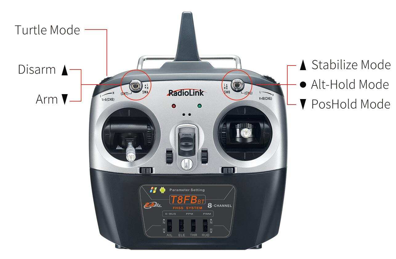
Take RadioLink T8FB as an example. PosHold mode, Alt-Hold mode and Stabilize mode are controlled by SWB of T8FB. SWA of T8FB is used to arm/disarm the aircraft. VrA of T8FB (Roll to the far right to turn it on; roll to the far left to turn it off) is used to switch the turtle mode. The manual mode is controlled by channel 10 by default. If you want to use the manual mode, please refer to the below steps to modify the manual mode channel to channel 6 in Mission Planner. The method is the same for other 8-channel transmitter.
Open Mission Planner--Select the correct COM port, 115200 baud rate and connect.
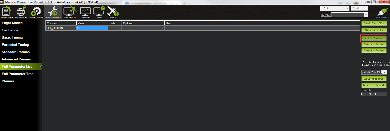
Click CONFIG/TUNING--Full Parameter List--Search.
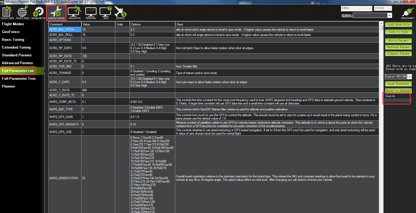
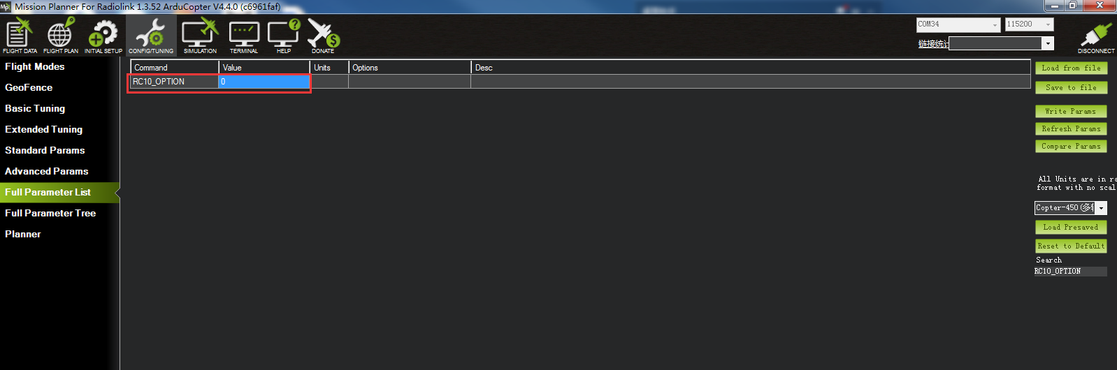
Search RC10_OPTION, modify the value to 0.
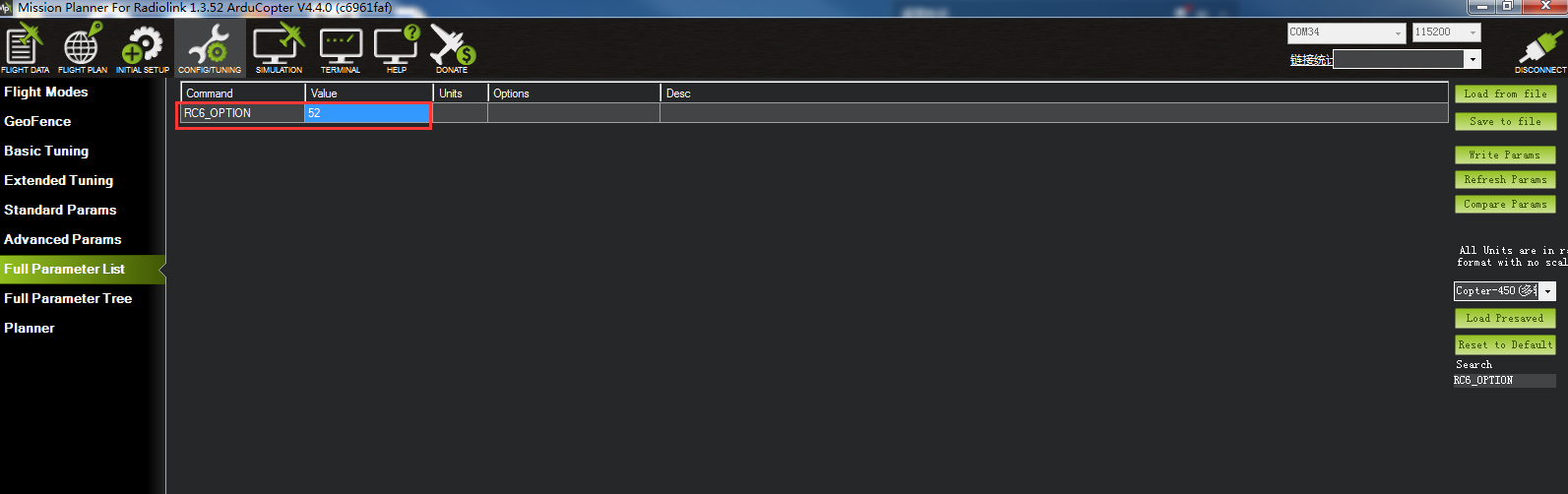
Search RC6_OPTION, modify the value to 52, which means to modify the manual mode channel to channel 6. (If you want to modify the channel to channel x, modify the value of RCx_OPTION)
Click Write Params to save the modification.
Thank you again for choosing RadioLink products.
If the above communication cannot solve your problem, you can also send emails to our technical support: after_service@radiolink.com.cn
Thank you again for choosing the RadioLink product.